Texas Instruments SN74HCT273N SN74HCT273N Flip-Flop With Clear Non Inverted Positive Edge 74HCT273 D 12 ns 37 MHz 4 mA DIP
The SN74HCT273N is an octal positive-edge-triggered D-type Flip-flop with clear and common enable input. The HCT273 devices are similar to the HCT377 devices, but feature a common clear enable (CLR\) input instead of a latched clock. Information at the data (D) inputs meeting the setup time requirements is transferred to the Q outputs on the positive-going edge of the clock (CLK) pulse. Clock triggering occurs at a particular voltage level and is not directly related to the positive-going pulse. When CLK is at either the high or low level, the D input has no effect at the output. The circuits are designed to prevent false clocking by transitions at (CLR\).
- Outputs can drive up to 10 LSTTL loads
- Inputs are TTL-voltage compatible
- Typical tpd = 12ns
- 80µA Maximum low power consumption
- ±4mA Output drive at 5V
- 1µA Maximum low input current
Industrial
Other details
| Brand | TEXAS INSTRUMENTS |
| Part Number | SN74HCT273N |
| Quantity | Each |
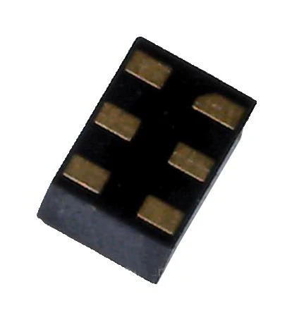
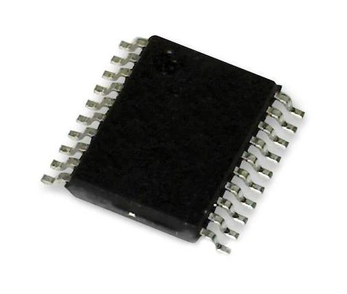
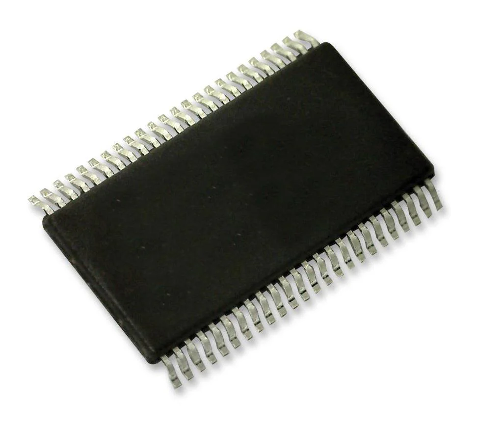
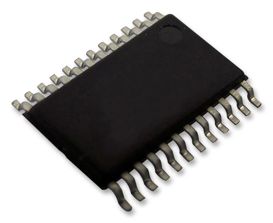
All product and company names are trademarks™ or registered® trademarks of their respective holders. Use of them does not imply any affiliation with or endorsement by them. Image is for illustrative purposes only. Please refer to product description.
$1.56
Texas Instruments SN74HCT273N SN74HCT273N Flip-Flop With Clear Non Inverted Positive Edge 74HCT273 D 12 ns 37 MHz 4 mA DIP—
$1.56
Product Information
Product Information
Shipping & Returns
Shipping & Returns
Description
The SN74HCT273N is an octal positive-edge-triggered D-type Flip-flop with clear and common enable input. The HCT273 devices are similar to the HCT377 devices, but feature a common clear enable (CLR\) input instead of a latched clock. Information at the data (D) inputs meeting the setup time requirements is transferred to the Q outputs on the positive-going edge of the clock (CLK) pulse. Clock triggering occurs at a particular voltage level and is not directly related to the positive-going pulse. When CLK is at either the high or low level, the D input has no effect at the output. The circuits are designed to prevent false clocking by transitions at (CLR\).
- Outputs can drive up to 10 LSTTL loads
- Inputs are TTL-voltage compatible
- Typical tpd = 12ns
- 80µA Maximum low power consumption
- ±4mA Output drive at 5V
- 1µA Maximum low input current
Industrial
Other details
| Brand | TEXAS INSTRUMENTS |
| Part Number | SN74HCT273N |
| Quantity | Each |
All product and company names are trademarks™ or registered® trademarks of their respective holders. Use of them does not imply any affiliation with or endorsement by them. Image is for illustrative purposes only. Please refer to product description.